
Getting started
Build a small desk-organizer set — tray, pen cup, scooped bin, and phone stand — in about ten minutes, and meet the tools you'll reach for every session.
Hew runs in two places: as a web app at app.hew3d.com, with nothing to install and no account required, and as a native desktop app for macOS, Windows, and Linux (see Download). Both are the same application; this guide works in either.
Rather than draw one lonely box, you’ll build something you could actually print: a little desk-organizer set — a tray holding a pen cup, a bin with a scooped front, and a phone stand. It touches the tools you’ll use in almost every session, and it takes about ten minutes.
The one idea that matters
Hew feels like SketchUp, but it is built around a single rule: every closed shape you push/pull becomes a discrete, watertight solid — an Object — and Objects never fuse just because they touch. The four parts of the organizer will sit on the tray, share edges, even overlap, and stay four separate things. When you do want two solids to become one, you say so. Watch for that idea; the whole app follows from it.
1. Draw the tray
Pick the Rectangle tool — click it in the tool rail on the left, or press R. The status bar along the bottom always spells out what the current tool wants next.
- Click once on the ground plane to set the first corner.
- Move the cursor. A live preview follows, and once the first corner is down, a measurement box appears in the top-right of the viewport tracking the width × depth.
- Click again to set the opposite corner.
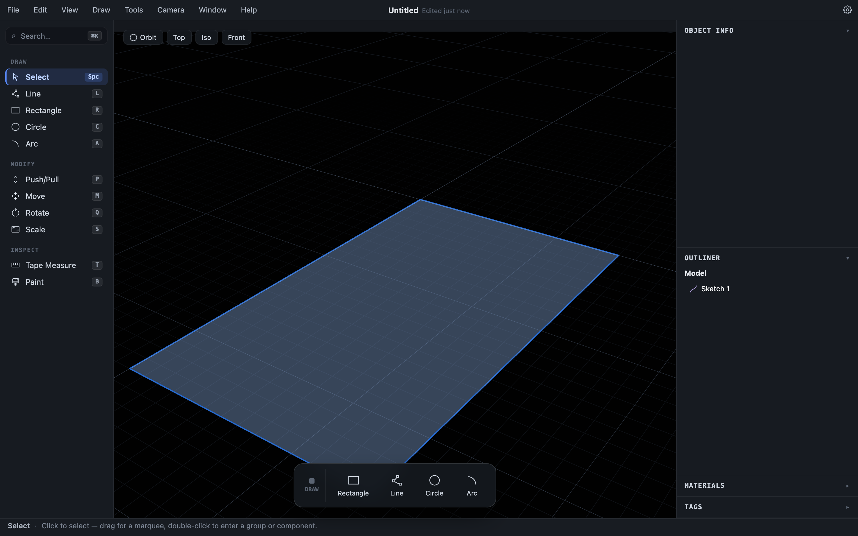
The closed rectangle fills in as a sketch region — you’ll see it as a Sketch in the Outliner on the right. As you draw, notice the colored dot and label at the cursor: Hew’s inference engine is calling out endpoints, midpoints, and axis alignments, the way SketchUp does.
Type the size instead of eyeballing it. You don’t click into that measurement box — Hew is listening whenever a tool is active. After the first corner, just type 24cm,14cm (or 9.5",5.5", or 0.24m,0.14m) and press Enter; your keystrokes land in the box and set the exact size. Precision, measurement, and guides lists every accepted format.
2. Push/pull it into a solid
Switch to Push/Pull (P):
- Click the rectangle.
- Move the cursor up and away; a live preview of the extrusion follows.
- Click to set the height, or type
1.5cmand pressEnter.
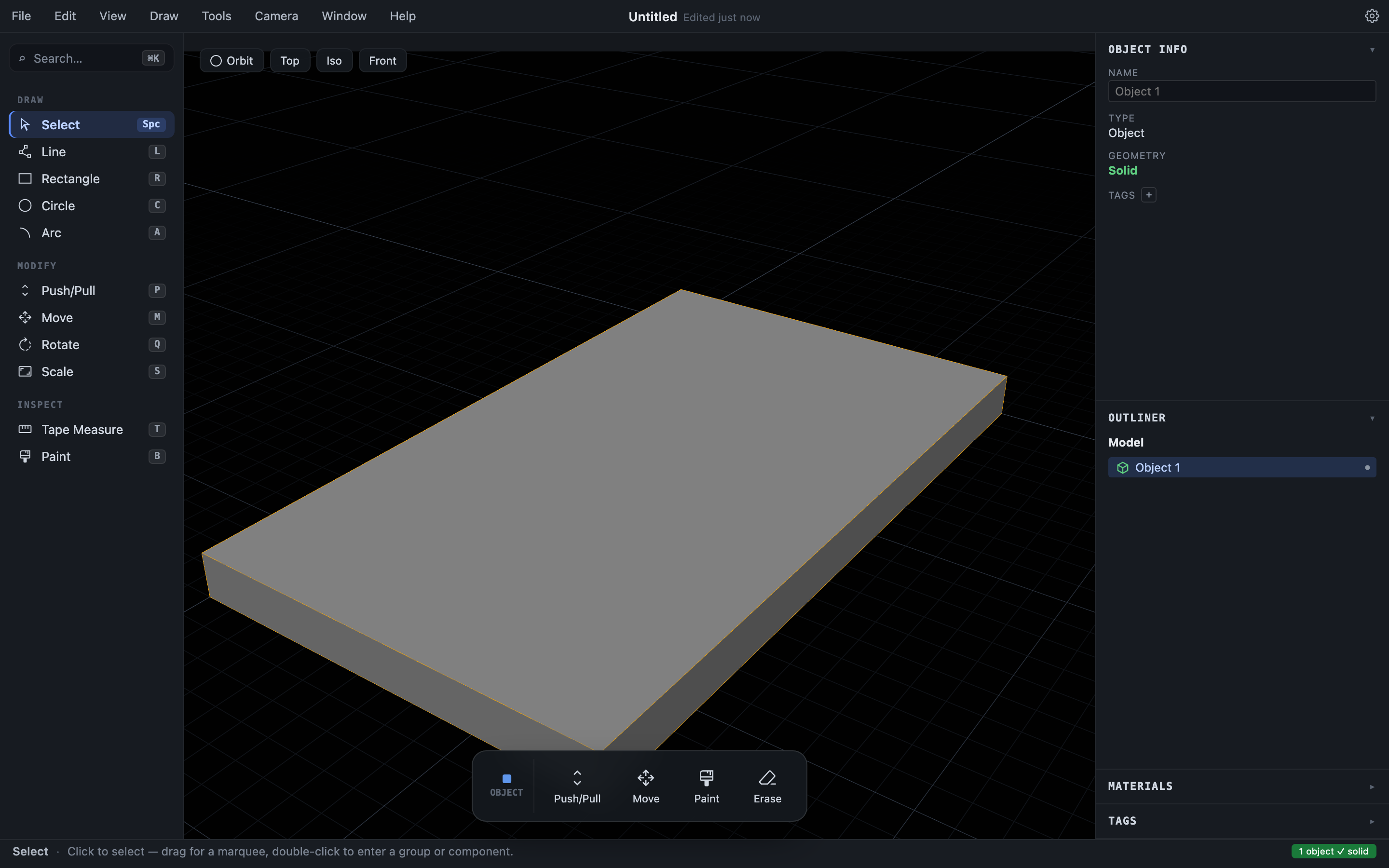
That’s your tray. The moment you commit, Hew turns the sketch into a real Object — a watertight solid. There’s no separate “make it a group” or “make it solid” step; push/pulling a closed profile is that step. Press Space for the Select tool and click the board: Object Info reads Solid, and the badge at the bottom-right of the status bar confirms every object in the model is watertight.
Look around while you work
Navigation is always available, whatever tool is active. Drag the middle mouse button to orbit, drag the right mouse button to pan, and scroll to zoom toward the cursor. No mouse wheel? Press O, H, or Z for Orbit, Pan, and Zoom and drag with the left button. The Top / Iso / Front buttons above the viewport jump to standard views, and Camera ▸ Zoom Extents frames everything. There’s more in Viewing your model.
3. The pen cup
Two new moves here: drawing a circle, and hollowing a solid by pushing a face inward.
- Pick the Circle tool (
C), click a center point on the ground beside the tray, type3cm, and pressEnter. What you type is the radius, so this makes a 6 cm-wide disk. - With Push/Pull (
P), click the disk and pull it up to9cm. You now have a solid cylinder. - Hollow it. To draw on a solid instead of on the ground, you first step inside it: double-click the cylinder — the rest of the scene dims, and you’re now editing just that Object. With the Circle tool, click the center of its top face and type
2.4cm; then take Push/Pull (P) and push that inner disk down7.5cm. Pushing a face inward carves a recess, leaving a 1.5 cm floor — the cup is now a cup. PressEscto step back out. - Switch to Select (
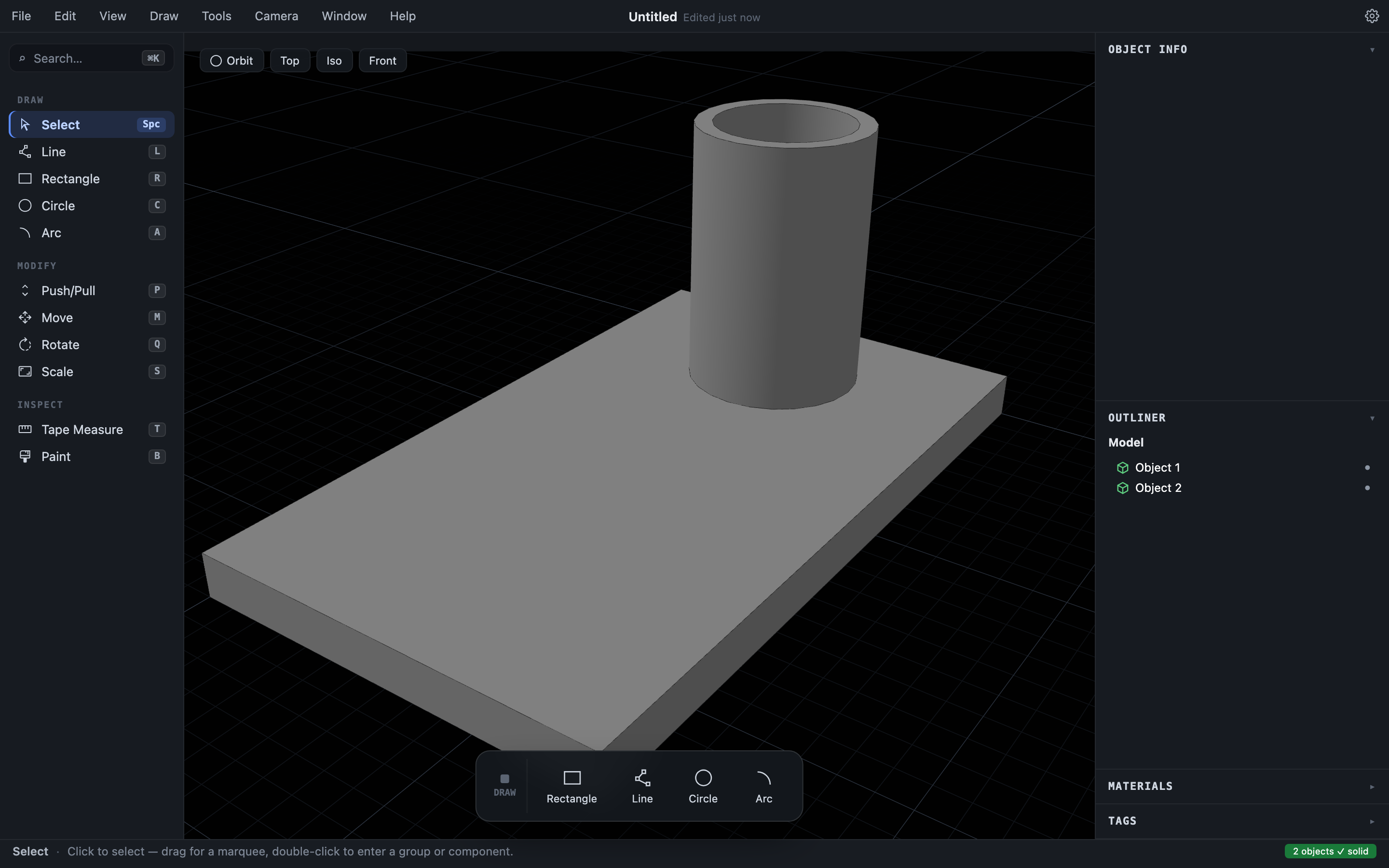
Space) and click the cup, then pressMfor Move and drag it onto the tray. (Move acts on the current selection, so select first, then move.) Because it’s its own Object, it rests on the tray without merging into it.
4. The bin with a scooped front
The bin starts as a hollow box, then gets its front scooped. The scoop is the one place in this build where you explicitly combine two solids.
- Rectangle (
R) → a7cm,5cmfootprint on the ground; Push/Pull (P) up6cminto a solid block. - Hollow it, the same way you hollowed the cup — you have to be inside the solid to draw on it. Double-click the block to step in, draw a Rectangle (
R) on its top face leaving roughly a0.7cmwall all the way around, then Push/Pull (P) that inner rectangle down5cm(a1cmfloor). PressEscto step out. You now have an open box. - Make the cutter for the scoop: off to the side, with Circle (
C, radius2cm) and Push/Pull (P), stand up a cylinder about8cmtall. - Bring them together — and here you rotate the bin, not the cylinder. Select the bin, press
Qfor Rotate, hover one of its lower edges to set the axis, and tip it90°onto its side so the top edge of the front wall stands vertical, right beside the upright cylinder. Move (M) the bin until the cylinder bites into that edge. - Select the bin,
Shift-click the cylinder, and choose Edit ▸ Subtract. The cylinder carves a smooth curved dip along the rim and vanishes, leaving one watertight bin. - Rotate (
Q) the bin upright again, then Move (M) it onto the tray.
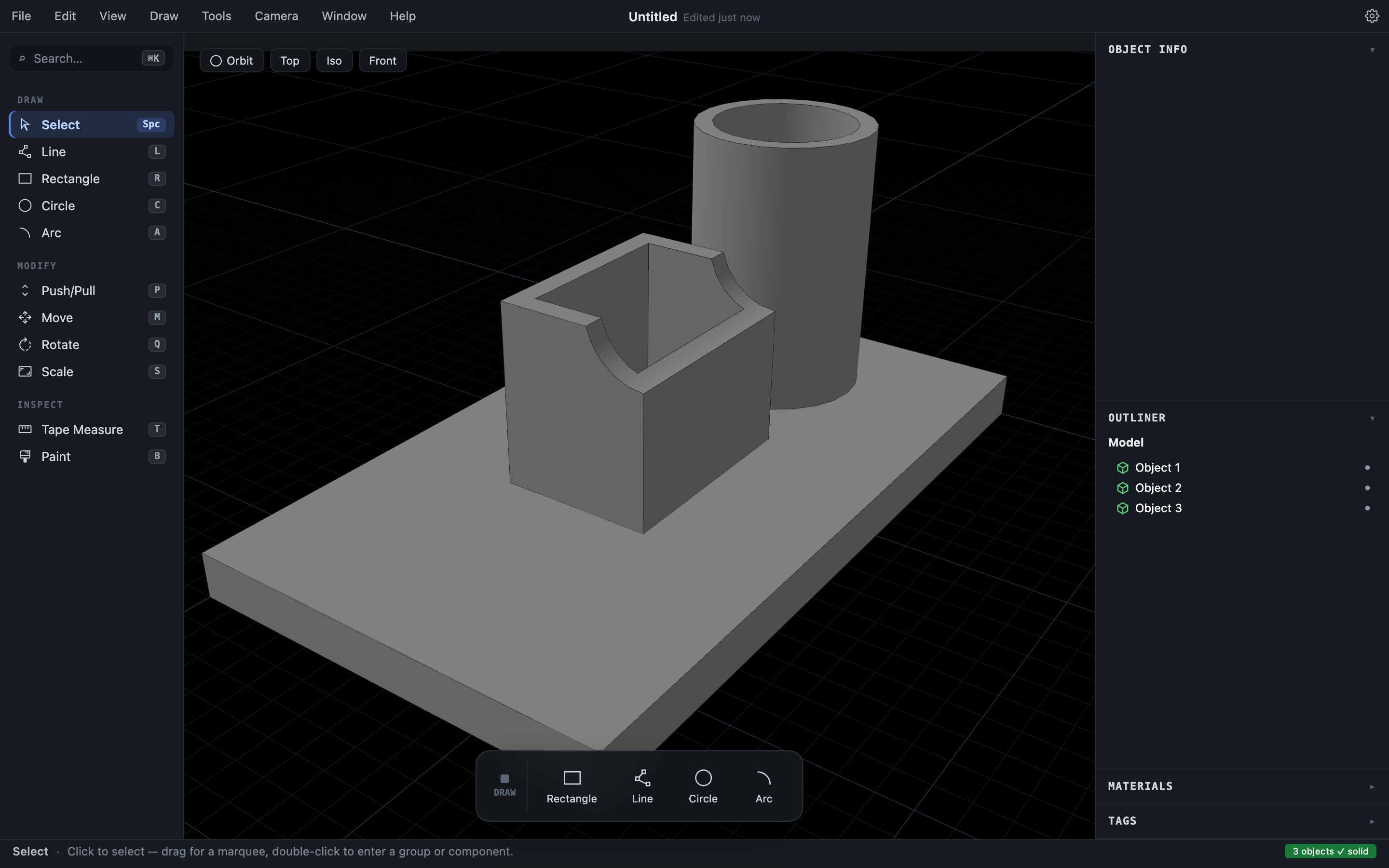
Rotating the cylinder onto its side instead — so the bin never has to move — is quicker once you’re comfortable, but a cylinder’s curved wall gives the Rotate tool no flat face to aim at, so you’d first press an arrow key (→ / ← / ↑) to lock the X / Y / Z axis. Rotating the box is the gentler way in. Subtract is one of three booleans (with Union and Intersect); Combining and splitting solids covers when to reach for each, and when — as with the hollowing — Push/Pull already does the job.
5. The phone stand
The stand is a wedge: a tall back, a slope for the phone to lean on, and a 1cm lip at the front so it can’t slide off. Drawing that sloped profile freehand is fiddly — the easy way starts from a plain rectangle, and introduces two tools you’ll use constantly: guide lines, and editing a sketch after the fact.
- Rectangle (
R) → a6cm,8cmrectangle on the ground beside the tray. That’s the profile’s bounding box: 6 deep, 8 tall. - Press
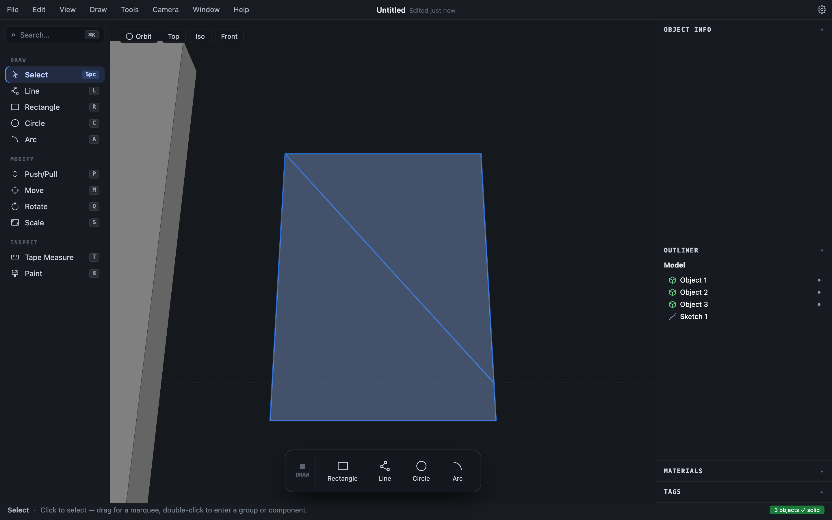
Tfor Tape Measure and click the rectangle’s bottom line, then move upward — a guide line parallel to that edge follows the cursor. Type1cmand pressEnterto pin it exactly 1 cm up. Guides are construction lines: they never become geometry, they just give the next tool something to snap to. - With the Line tool (
L), draw one line from the point where the guide crosses the rectangle’s front edge — watch for the amber Intersection snap — up to the rectangle’s back top corner. The diagonal splits the rectangle into two filled regions.
- Switch to Select (
Space) and delete the two lines you no longer need: click the rectangle’s top edge and pressDelete, then click the short piece of the front edge above the diagonal and pressDelete. Each deletion updates the sketch — what’s left filled in is the wedge profile. Edit ▸ Delete Guide Lines clears the guide, its job done. - Push/Pull (
P) the wedge region5cmwide. - Select the wedge, press
Qfor Rotate, hover a bottom edge to set the axis, and tip it90°so the slope faces up. (It’s a box-like shape with flat faces, so Rotate has an easy time.) Then Move (M) it onto the tray next to the bin.
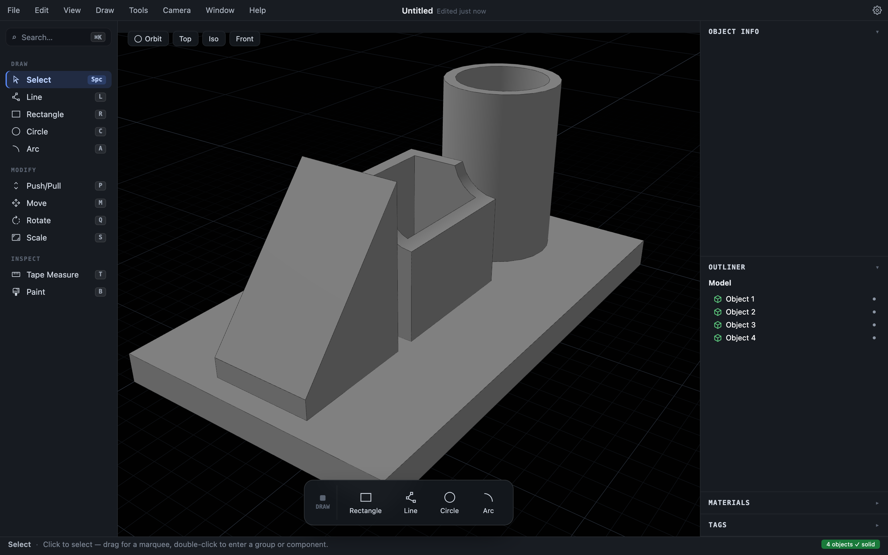
Four parts, four Objects. They touch and overlap on the tray, and the status bar still reads four solids: nothing merged on its own.
6. Paint the parts
Expand Materials in the right-hand tray. Click Add color, pick a wood tone, and name it Oak; add a few more — a teal, a terracotta, a slate.
To paint a whole part, click the swatch you want — that picks up the Paint tool — then ⌘/Ctrl-click the part to fill it. Do that for each of the four. (A plain click paints one face at a time.)
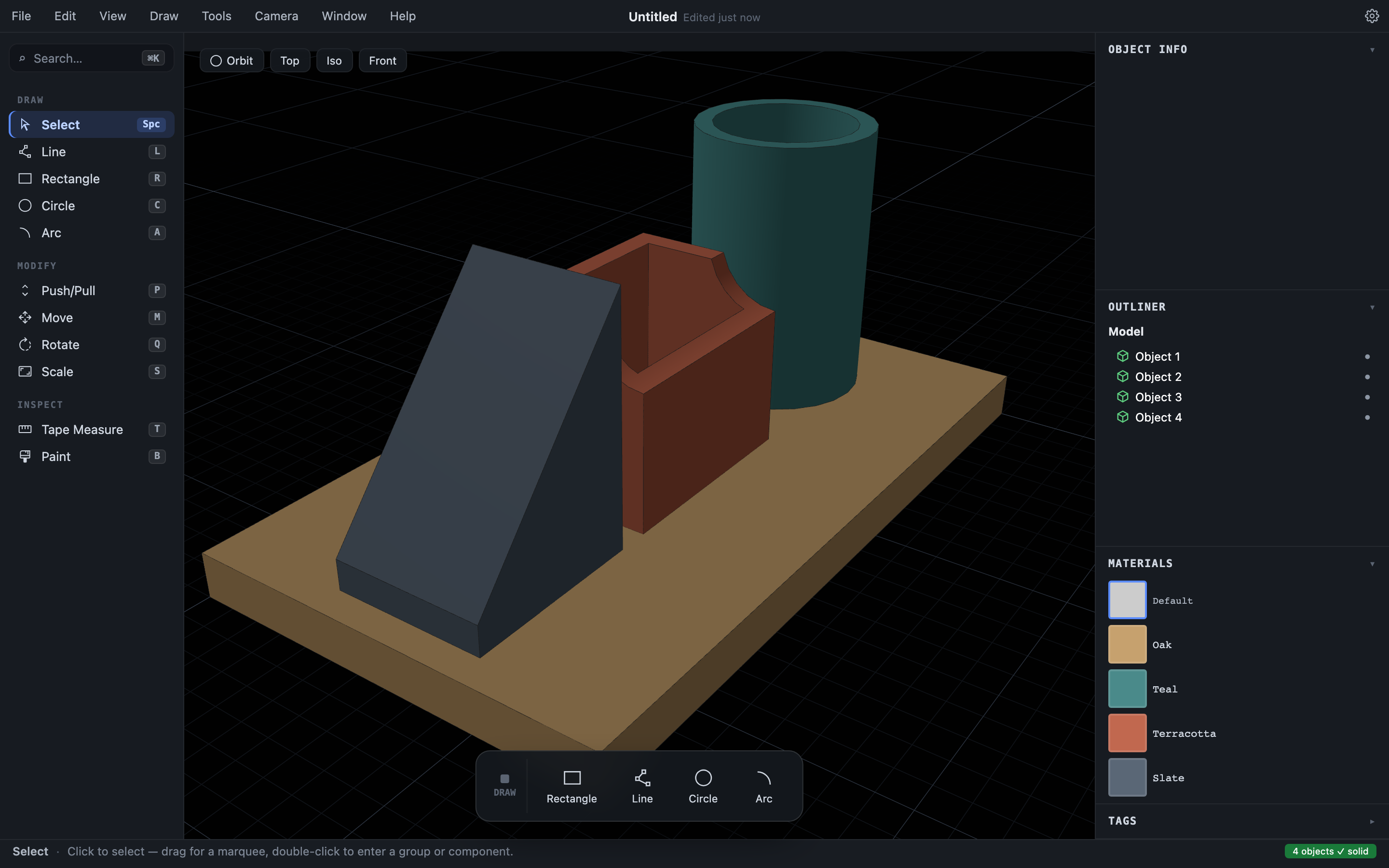
Materials are per-document and they survive modeling: paint follows the geometry through push/pull, slicing, and booleans. See Materials for textures and opacity.
7. Name it, group it, tag it
A model with four “Object N” rows is already worth tidying.
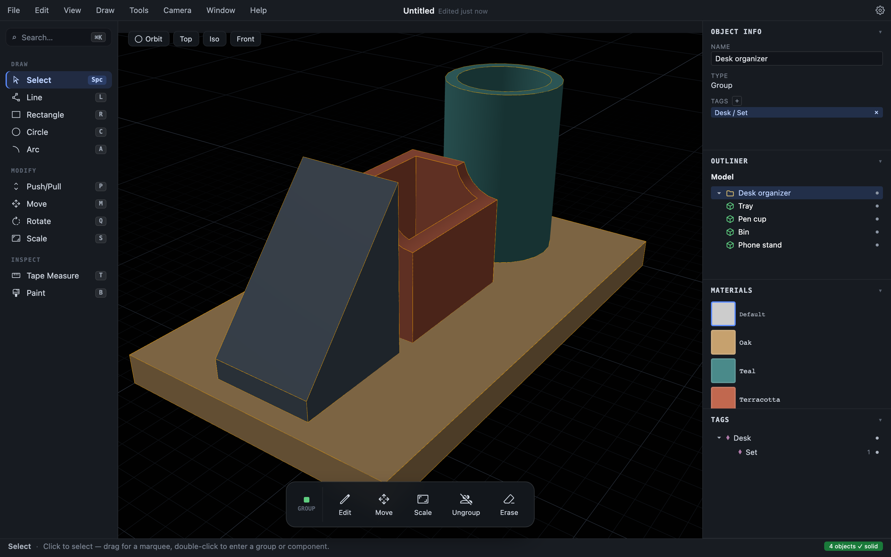
- Select each part and, in Object Info, type a real Name — Tray, Pen cup, Bin, Phone stand — pressing
Enterafter each. - Select all four (
⌘A/Ctrl+A) and choose Edit ▸ Group (⌘G/Ctrl+G). Name the group Desk organizer. Now the whole set moves, hides, and selects as one, while the parts stay separate inside it. - With the group selected, click + next to Tags in Object Info and type
Desk/Set. The Tags panel shows the tag tree; tags slice a model into show/hide categories independent of the group structure.
Organizing your model goes deeper on the Outliner, tags, and visibility.
8. Save, then export to print
Save the Hew document with ⌘S / Ctrl+S (or File ▸ Save). The native format is .hew — an open container that keeps geometry, names, groups, materials, and tags together, and saves byte-for-byte identically each time. Hew also autosaves a recovery snapshot every 12 seconds, so a crash won’t cost you the session (Files, saving, and recovery).
To print, choose File ▸ Export…, pick STL binary (.stl), and click Export.
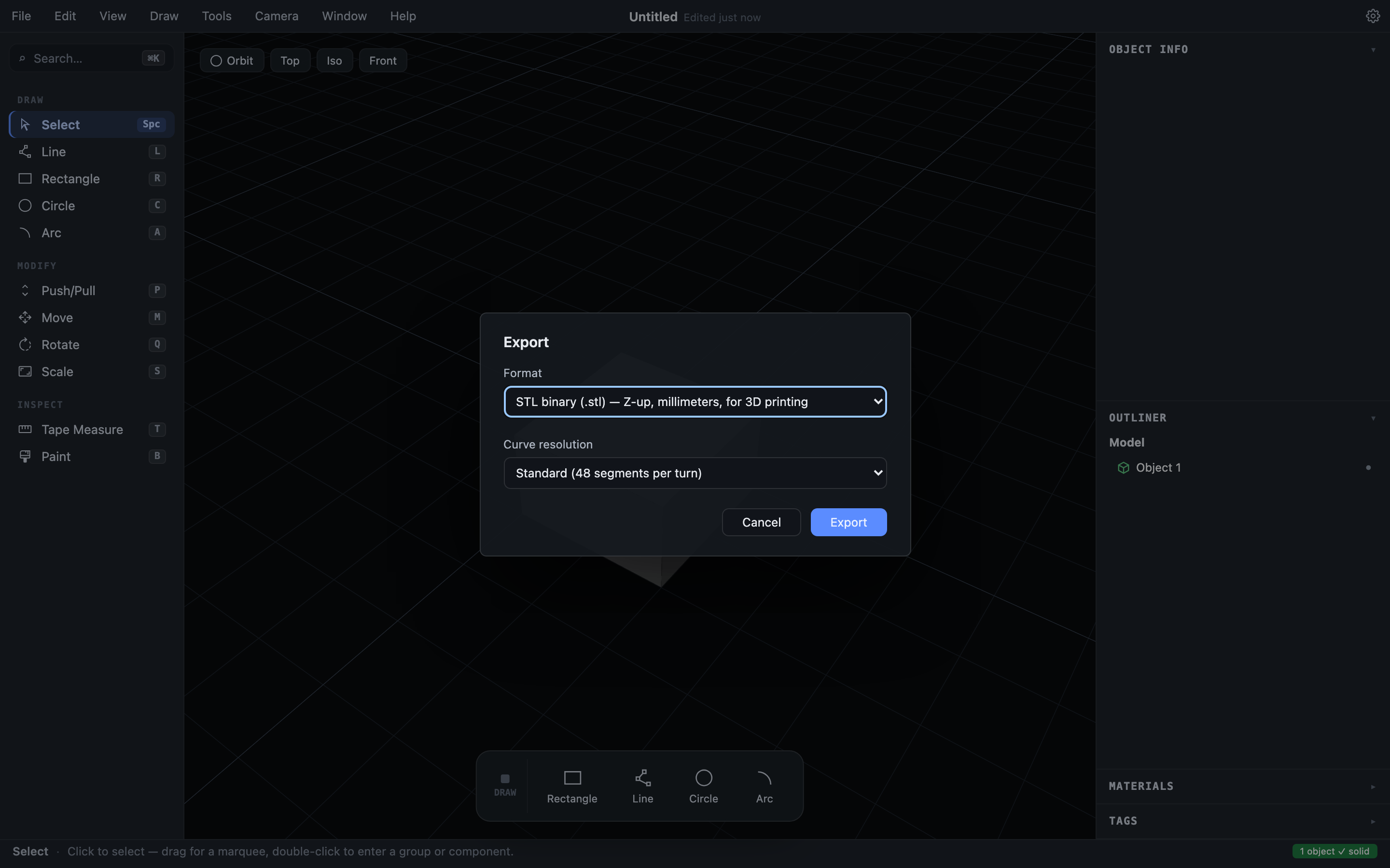
Because every Object is watertight by construction, the STL is manifold — no gaps, flipped normals, or open shells for your slicer to repair. If anything in the model weren’t solid, Hew would warn you and name it rather than hand you a broken file. The mesh exports in millimeters, ready for any slicer.
Where to go next
You’ve drawn, measured, pushed, hollowed, subtracted, rotated, edited a sketch, painted, organized, and exported — the moves behind most of what you’ll model. From here:
- Core concepts explains the ideas that make Hew diverge from SketchUp as models get complicated.
- The Hew interface tours every panel and control.
- Drawing and Push/Pull are the full drawing-and-modeling reference.